


Description of the MBBR (Moving Bed Biofilm Reactor) Process

 Email:Kate@aquasust.complastic.com
 Initial Development of the MBBR Process:
The MBBR process for wastewater treatment was invented and initially developed by Professor Hallvard Ǿdegaard in the late 1980s at the Norwegian University of Science and Technology.
there were already more than 800 MBBR wastewater treatment plants in more than 50 countries in 2014, with about half treating domestic wastewater and about half treating industrial wastewater. At least part of the reason for the interest in the MBBR process is its small footprint in comparison with other biological treatment processes. The tank volume needed for an MBBR process is typically significantly less than that needed for either an activated sludge process or a trickling filter designed to treat the same wastewater flow.
 General Description of the MBBR Process:
The MBBR process is an attached growth biological wastewater treatment process. That is, the microorganisms that carry out the treatment are attached to a solid medium, as in trickling filter or RBC systems. By contrast, in a suspended growth biological wastewater treatment process, like the activated sludge process, the microorganisms that carry out the treatment are kept suspended in the mixed liquor in the aeration tank.
In the conventional attached growth biological treatment processes, like trickling filter or RBC systems, the microorganisms are attached to a medium that is fixed in place and the wastewater being treated flows past the surfaces of the medium with their attached biological growth. In contrast, an MBBR process utilizes small plastic carrier media (described in more detail in the next section) upon which the microorganisms are attached. The MBBR treatment processes typically take place in a tank similar to an activated sludge aeration tank. The carrier media are kept suspended by a diffused air aeration system for an anaerobic process or by a mechanical mixing system for an anoxic or anaerobic process, as illustrated in the figures below. A sieve is typically used at the MBBR tank exit to keep the carrier media in the tank.
The primary clarification is typically used ahead of the MBBR tank. Secondary clarification is also typically used, but there is no recycle-activated sludge sent back into the process because an adequate microorganism population is maintained attached to the media.


 The MBBR Media Support Carrier System:
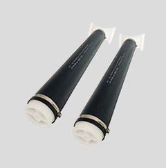
MBBR processes use plastic media support carriers similar to those shown in the figure below. As shown in that figure, the carrier is typically designed to have a high surface area per unit volume, so that there is a lot of surface area on which the microorganisms attach and grow. Media support carriers like those shown in the figure are available from numerous vendors. Two properties of the carrier are needed for the process design calculations to be described and discussed in this course. Those properties are the specific surface area in m 2 /m 3 and the void ratio. The specific surface area of MBBR carriers is typically in the range from 350 to 1200 m 2 /m 3 and the void ratio typically ranges from 60% to 90%. Design values for these carrier properties should be obtained from the carrier manufacturer or vendor.

MBBR Wastewater Treatment Process Alternatives:
The MBBR wastewater treatment process is quite flexible and can be used in several different ways. The figure below shows flow diagrams for the following six alternatives. Note that, as previously mentioned, primary clarification and secondary clarification are shown for all of the
process alternatives, but there is no sludge recycle as in a conventional activated sludge process.
1. Single stage BOD removal
2. Two stage BOD removal
3. Two stage BOD removal and Nitrification
4. Single stage tertiary Nitrification
5. Pre-Anoxic Denitrification
6. Post-Anoxic Denitrification

Overview of MBBR Process Design Calculations:
The key empirical design parameter used to determine the required MBBR tank size is the surface area loading rate (SALR) in g/m 2 /d. The g/d in the SALR units refers to the g/d of the parameter being removed and the m 2 in the SALR units refers to the surface area of the carrier. Thus, for BOD removal the SALR would be g BOD/day entering the MBBR tank per m 2 of carrier surface area. For a nitrification reactor, the SALR would be g NH 3 -N/day entering the MBBR tank per m 2 of carrier surface area. Finally, for denitrification design, the SALR would be g NO 3 -N/day per m 2 of carrier surface area.
For any of these processes, a design value for SALR can be used together with design values of wastewater flow rate and BOD, ammonia, or nitrate concentration, calculate the required carrier surface area in the MBBR tank. The design carrier volume can then be calculated using a known value for the carrier-specific surface area (m 2 /m 3 ). Finally, a design value for the carrier fill % can be used to calculate the required tank volume.

 MBBR61
Patent NO.:ZL2020 30250198.5
Size:Φ25*4mm Hole Numbers:06
Material: 100% White Virgin HDPE Weight:125KG/CBM
Densilty:0.96-0.98g/cm3
Surface Area:>1250m2/m3

MBBR19
Size:Φ25*12mm Hole Numbers:19
Material: 100% White Virgin HDPE Weight:95KG/CBM
Densilty:0.96-0.98g/cm3
Surface Area:>650m2/m3
")
MBBR37
Size:Φ25*12mm, Hole Numbers:37
Material: 100% White Virgin HDPE Weight:105Kg/CBM
Densilty:0.96-0.98g/cm3
Surface Area:>800m2/m3