





In Moving Bed Biofilm Reactor (MBBR) systems, the effluent retention screen (sieve) serves as the indispensable mechanical barrier that retains fluidized carriers within the biological reaction basin while allowing treated wastewater to discharge freely. In global wastewater treatment operation logs, two of the most frequent operational challenges are effluent backup caused by localized screen blinding and downstream pump clogging resulting from carrier migration through damaged or incorrectly sized screens.
Retention screen engineering extends far beyond simple perforated sheet metal. It requires an integrated design encompassing fluid hydrodynamics, hydraulic head loss modeling, mechanical fatigue resistance, and continuous self-cleaning turbulence. This technical article provides a comprehensive engineering analysis of wedge wire versus perforated plate configurations, mathematical formulations for head loss prediction, and proven anti-clogging operational protocols.
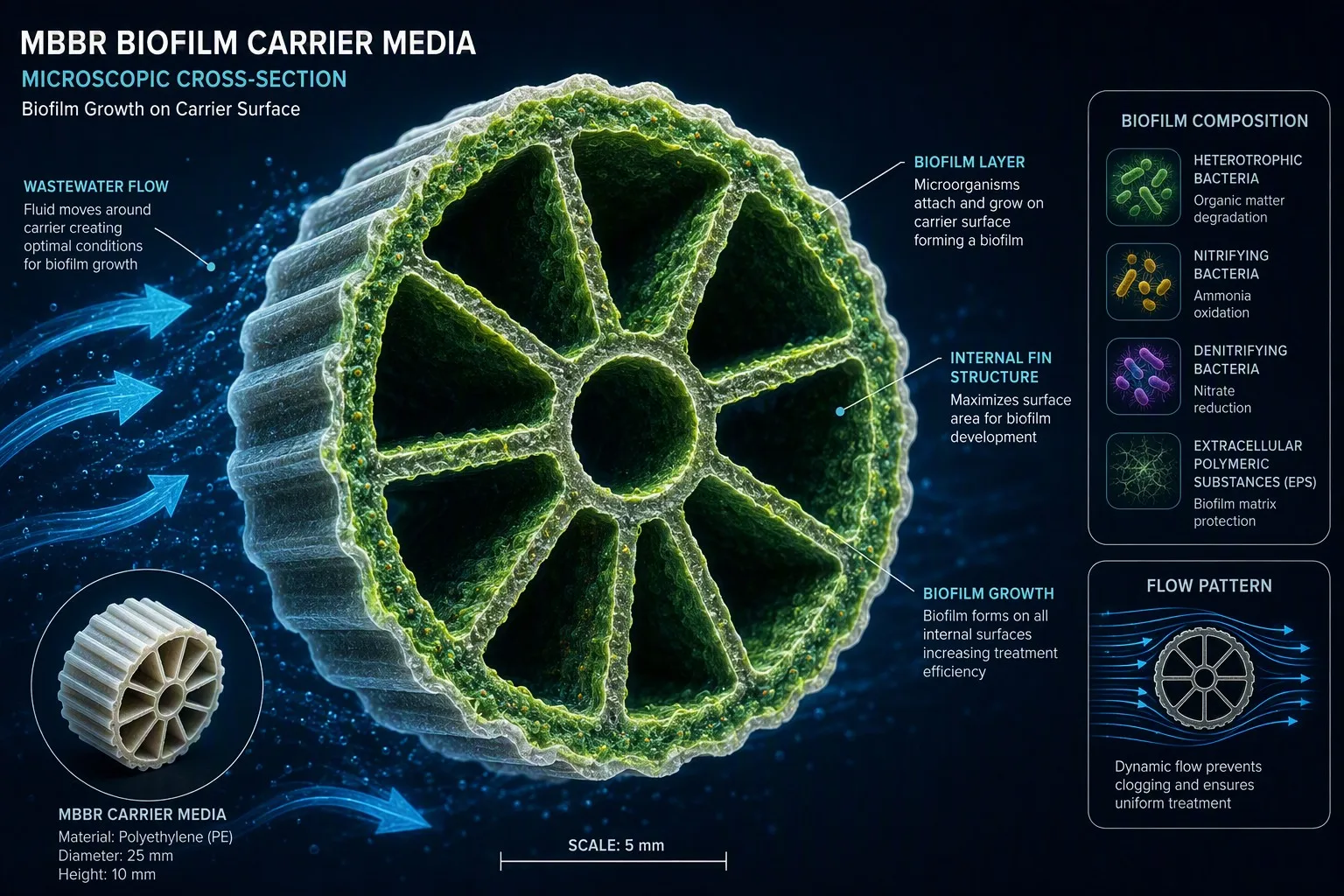
Figure 1: Aquasust high-strength stainless steel wedge wire retention sieve cylinder maintaining micro-gap barrier integrity under intensive basin fluidization.
1. Screen Geometry Comparison: Wedge Wire (V-Wire) vs. Perforated Plate
Modern MBBR installations predominantly employ two mechanical screening configurations:
1.1 Continuous Slot Wedge Wire Screens (V-Profile Wire)
Wedge wire screens are fabricated by resistance-welding continuous V-shaped wire onto internal longitudinal support rods:
- Single-Point Particle Contact: The continuous slot widens inward, creating a profile where the opening is narrowest at the face. Particles or irregular biofilm fragments smaller than the opening pass through without lodging, virtually eliminating mechanical blinding;
- High Open Area Ratio: With standard slot openings (e.g., 5.0 – 8.0 mm), wedge wire screens achieve 35% – 55% open area, compared to less than 20% – 28% for conventional perforated plates;
- Low Hydraulic Resistance: The streamlined aerodynamic profile of the smooth wire surfaces reduces eddy turbulence and minimizes localized head loss.
1.2 Perforated Plates: Operational Boundaries and Limitations
While perforated plates offer lower initial fabrication costs, their straight-walled circular or slotted perforations are susceptible to progressive carrier jamming. Fluidized carriers colliding at an angle can become mechanically lodged in circular holes, while shedding biofilm sloughs tend to accumulate inside cylindrical edges, creating biological biofouling.
2. Slot Opening Sizing and Approach Velocity Standards
Achieving 100% media retention while minimizing head loss requires rigorous aperture sizing based on carrier geometry:
2.1 Slot Opening Sizing Rule
The screen slot opening (Slotwidth) must not exceed 65% of the carrier's minimum physical dimension (Dmin,media):
Slotwidth ≤ 0.65 × Dmin,media
For standard ∅25 × 10 mm carriers (e.g., AS-MBBR-19), the minimum dimension is 10 mm length, setting the maximum slot opening at 6.5 mm (standard engineering practice specifies 5.0 – 6.0 mm). For compact thin-disc media (e.g., ∅25 × 4 mm), slot openings must be reduced to 2.0 – 2.5 mm.
2.2 Approach Velocity Limits
Excessive approach velocity creates suction forces that pin carriers against the screen face, initiating progressive blinding. Engineering standards dictate:
- Clean Screen Design Approach Velocity: vapproach ≤ 0.15 – 0.25 m/s;
- Peak Flow Condition with 50% Fouling Safety Factor: vpeak ≤ 0.40 m/s.
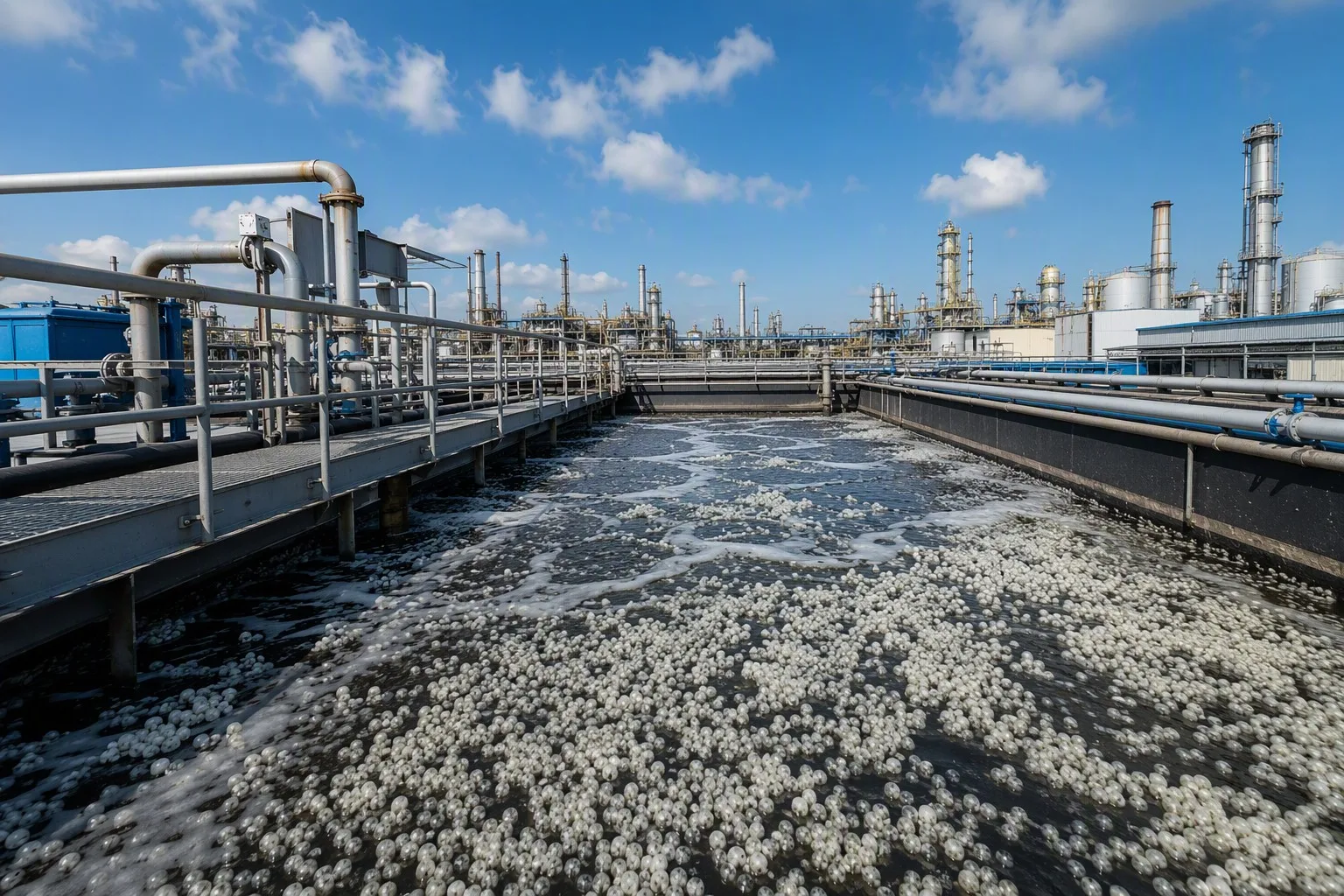
Figure 2: Modular stainless steel cylindrical retention screen assemblies installed in parallel within an industrial biological treatment train.
3. Hydraulic Head Loss Calculation Modeling
Localized head loss across clean and fouled screens is calculated using the modified orifice equation:
Δh = ξ × [ va² / (2g) ] × [ 1 / ( φ × (1 − β) ) ]²
Where:
- Δh: Total hydraulic head loss across the screen (m);
- ξ: Form drag loss coefficient (ξ = 1.2 – 1.5 for V-wire; ξ = 2.0 – 2.8 for perforated plates);
- va: Approach flow velocity upstream of screen (m/s);
- g: Acceleration of gravity (9.81 m/s²);
- φ: Nominal geometric open area ratio (0.35 – 0.50);
- β: Biofouling clogging safety factor (β = 0.10 – 0.20 for regular operation; β = 0.50 for peak safety design).
In well-engineered installations, clean screen head loss remains within 30 – 80 mm H₂O. Even under peak design flow with 50% biofouling, total head loss must not exceed 200 mm H₂O to avoid upstream basin overflow.
4. Retention Screen Technical Specifications Matrix
| Screen Configuration | Matched Media | Slot Width (mm) | Material Grade | Hydraulic Loading Rate | Self-Cleaning Mechanism |
|---|---|---|---|---|---|
| Horizontal Cylindrical Sieve | AS-MBBR-19 (∅25 × 10) | 5.0 – 6.0 (±0.1) | AISI 304 / 316L | 120 – 180 m³/(m²·h) | Bottom dedicated coarse bubble air scour |
| Vertical Insertion Cartridge | AS-MBBR-37 (∅25 × 12) | 4.0 – 5.0 (±0.1) | AISI 316L | 150 – 220 m³/(m²·h) | Air-lift circulating micro-bubble ring |
| Inclined Flat Panel Grating | AS-MBBR-S (∅25 × 10) | 6.0 – 8.0 (±0.2) | Duplex 2205 / 2507 | 100 – 140 m³/(m²·h) | Reciprocating mechanical scraper arm |
| Micro-Slot Precision Sieve | AS-MBBR-64 (Thin Disc) | 2.0 – 2.5 (±0.05) | AISI 316L / Titanium | 80 – 120 m³/(m²·h) | Pulsed backwash pneumatic sweep |
5. Environmental Considerations & Material Metallurgy
5.1 Coastal and High-Salinity Industrial Effluents (Southeast Asia & Middle East)
In seawater desalination outfalls or chemical facilities where chloride concentrations exceed 15,000 – 35,000 mg/L, standard AISI 304/316L screens experience rapid localized pitting and crevice corrosion within 3 to 6 months. These demanding applications require Duplex 2205 (EN 1.4462) or Super Duplex 2507 with post-weld chemical pickling and passivation to prevent catastrophic screen failure.
5.2 Cold Climate Municipal Wastewater (Europe & North America)
In low-temperature winter operations where biological sludge viscosity increases, screens must integrate dedicated Coarse Bubble Air Scour headers installed 200 – 300 mm beneath screen cylinders. An intermittent scouring air flow of 0.8 – 1.5 m³/(m²·min) creates buoyant shear bubbles that detach accumulating biomass and recirculate carriers back into the active mixing zone.
6. Frequently Asked Questions (FAQ)
Q1: What causes localized media accumulation and stagnant dead zones at the base of screen cylinders?
A: This typically occurs when process aeration diffusers do not reach beneath the screen cylinder, creating a hydraulic dead zone. Installing a perforated coarse bubble air pipe directly beneath the screen assembly provides upward turbulent lift, preventing carrier accumulation.
Q2: How should an MBBR basin be protected in the event of unforeseen screen structural failure?
A: High-reliability municipal and industrial designs implement a secondary emergency bar rack downstream in the effluent channel, paired with optical suspended solids sensors. Detectors trigger immediate automated closure of motorized effluent butterfly valves upon detecting escaping media, protecting downstream filtration and pumping units.
Engineered stainless steel wedge wire retention screens represent the critical balance between hydraulic efficiency and complete media retention. Contact Aquasust engineering teams for custom screen sizing calculations, hydraulic loss verification, and structural metallurgy support.