


In wastewater treatment systems, the layout of tube diffusers directly affects oxygen transfer efficiency, energy consumption control, and treatment performance. The arrangement of diffusers must be designed in combination with tank structure, treatment process, and water quality characteristics to ensure uniform bubble distribution and avoid localized anaerobic or over-aeration conditions. Common tube diffuser layouts include circular, branch, grid, swirl, and alternating configurations, each suited to different operating conditions.

Circular Layout
This arrangement is suitable for circular or annular reactors, such as oxidation ditch processes. Tube diffusers are installed concentrically or spirally along the tank wall, enhancing water circulation through uniform bubble rise paths. Key design parameters include pipe diameter (typically DN50–DN150) and ring spacing (0.8–1.5 m), with bubble coverage required to exceed 70% of the tank floor area. Pressure loss at bends should be minimized using 45° angled elbows.
Branch Layout
Commonly used in rectangular aeration tanks, this design features a main pipeline along the tank length with lateral branches extending in a fishbone pattern. Branch spacing is determined by the diffuser service area (e.g., 0.6–0.8 m for microporous diffusers). A drain valve must be installed at the main pipe end to prevent sludge accumulation. Air distribution can be adjusted via zone control valves to accommodate influent fluctuations.
Grid Layout
Typically applied in plug-flow aeration tanks, tube diffusers are arranged in a matrix to form a grid. Supports are required at pipeline nodes to prevent displacement by hydraulic forces. Grid spacing usually ranges from 0.5–1.2 m, adjusted based on MLSS levels (e.g., spacing ≤0.5 m for MLSS >3000 mg/L). The tank floor should have a 1%–2% slope to facilitate sludge movement toward discharge ports.
Swirl Layout
Designed for deep-shaft aeration tanks with high height-to-diameter ratios, diffusers are installed tangentially to generate rotational flow via rising bubbles. Optimal installation angles are 30°–45°, and anti-clogging swirl diffusers are recommended. This method achieves an air-to-water ratio up to 15:1, suitable for high-strength organic wastewater but requires high-pressure blowers.
Alternating Layout
Used in intermittent processes like alternating oxidation ditches, this system switches aeration zones via electric valves. Two independent pipe networks operate in cycles (e.g., 2-hour aeration/1-hour settling), with valves meeting IP68 sealing standards. Energy savings exceed 30%, but dual control systems are needed for reliability.

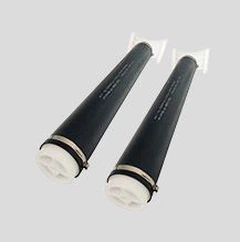
Material Selection and Installation
Tube diffuser materials must resist corrosion and ensure durability: EPDM rubber tubes for pH 6–9; silicone rubber tubes for pH 2–12. Pipes should be secured with 316L stainless steel clamps (spacing ≤1.5 m, reduced to 0.8 m at bends). Post-installation pressure testing at 1.5× working pressure for 30 minutes should show ≤5% pressure drop.
Operation and Maintenance
Regularly monitor aeration uniformity using dissolved oxygen (DO) probe arrays; investigate clogging if DO deviations exceed ±0.5 mg/L. Chemical cleaning frequency depends on water hardness: quarterly acid washing (5% citric acid for 2 hours) for calcium carbonate >200 mg/L. Physical cleaning can use high-pressure water jets (≥10 MPa) for backflushing diffuser membranes.