


1. What is MBBR and MBBR Full Form
2. Design of MBBR process
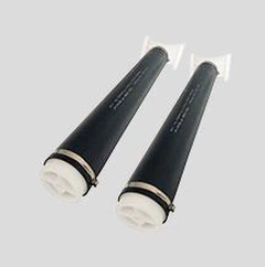
2.1 Introduction of biofilm carrier
2.2 Removal of carbonaceous substances
2.3 Design of high load MBBR
2.4 Design of conventional load MBBR
2.5 Design of low load MBBR
2.6 Nitrification of MBBR Technology
2.7 Denitrification of MBBR Tank
2.7.1 Moving bed biofilm reactor with pre-denitrification
2.7.2 Moving bed biofilm reactor with post-denitrification
2.7.3 Combined pre/post denitrification moving bed biofilm reactor
2.7.4 Agitation of denitrification
2.8 Pre-processing
2.9 Solid-liquid separation of MBBR
2.10 Considerations when designing MBBR
2.10.1 MBBR Traveling flow rate (horizontal flow rate)
2.10.2 MBBR Tank Foam problems
2.10.3 Carrier bed clearance and temporary storage

1.What Is MBBR And MBBR Full Form
Over the past 20 years, the Moving Bed Biofilm Reactor (MBBR) has evolved into a simple, robust, flexible and compact wastewater treatment process. Different configurations of MBBR have been successfully used for BOD removal, ammonia oxidation and nitrogen removal, and can meet different effluent quality criteria including stringent nutrient limitations.
The moving bed biofilm reactor uses specially designed plastic as the biofilm carrier, and through aeration stirring, liquid
The carrier can be suspended in the reactor by refluxing or mechanical mixing. In most cases, the carrier is filled between 1 /3 and 2/3 of the reactor. The versatility of the MBBR allows the design engineer to use his or her imagination to the fullest. The major difference between the MBBR and other biofilm reactors is that it combines many of the advantages of the activated sludge and biofilm methods while avoiding as many of their disadvantages as possible.
1) Like other submerged biofilm reactors, MBBR is capable of forming highly specialized active biofilms that can be adapted to the specific conditions within the reactor. The highly specialized active biofilm results in a high efficiency per unit volume of the reactor and increases the stability of the process, thereby reducing the size of the reactor.
2) The flexibility and process flow of MBBR is very similar to that of activated sludge, allowing multiple reactors to be sequentially arranged along the flow direction to meet multiple treatment objectives (e.g. BOD removal, nitrification, pre- or post-denitrification) without the need for an intermediate pump.
3) Most of the active biomass is persistently retained in the reactor, so unlike the activated sludge process, MBBR The solids concentration in the MBBR effluent is at least as high as the solids concentration in the reactor. The MBBR is an order of magnitude lower than the traditional sedimentation tank, so in addition to the traditional sedimentation tank, the MBBR can use a variety of different solid-liquid separation Processes.
4) MBBR is versatile and the reactor can have different geometries. For retrofit projects, MBBR is well suited for the retrofit of existing ponds.
2. Design Of MBBR Process
The design of MBBR is based on the concept that multiple MBBR form a series, each with a specific function, and that these MBBR work together to accomplish the task of wastewater treatment. This understanding is appropriate because under the unique conditions provided (e.g. available electron donors and electron acceptors), each reactor is capable of cultivating a specialized biofilm capable of being used to achieve a particular treatment task. This modular approach can be viewed as a simple and straightforward design consisting of a sequence of multiple fully mixed reactors, each with a unique treatment purpose. In contrast, the design of activated sludge systems is very complex: since competitive reactions are always occurring, in `order to achieve the desired treatment objective within the residence time limited by each part of the tank (aeration and non-aeration zones), the total biosolids residence time (SRT) must be maintained at a suitable level so that bacteria can mix (in relation to bacterial growth rates and raw water properties) and grow together.
It is the simplicity of MBBR that allows us to understand the biofilm in MBBR well in practice through the observations of researchers, engineers and wastewater treatment plant operators. The majority of this paper presents examples of MBBR observations, thereby demonstrating those that are critical components and factors to consider in MBBR design and operation.
2.1 Introduction Of Biofilm Carrier
The key to the success of any biofilm reactor is to maintain a high percentage of bioactive volume within the reactor. If converting the biomass concentration on MBBR carriers to suspended solids concentration, the values are generally around 1000 to 5000 mg/l. In terms of unit volume, the removal rate of MBBR is much higher than that of activated sludge systems. This can be attributed to the following.
1) The shear force applied to the carrier by the mixing energy (e.g. aeration) effectively controls the thickness of the biofilm on the carrier, thus maintaining a high total biological activity.
2) The ability to maintain a high level of dedicated biomass under specific conditions within each reactor, independent of the total HRT of the system.
3) The turbulent flow condition in the reactor maintains the required diffusion rate.
Moving bed reactors can be used for BOD removal, nitrification and denitrification, and thus can be combined into different processes. Table 1-1 summarizes the various processes of MBBR. The determination of the most efficient process is related to the following factors.
1) Local conditions, including layout and hydraulic cross-section (elevation) of the wastewater treatment plant.
2) Existing treatment processes and the possibility of modifying existing facilities and ponds.
3) Target water quality.
Table 1-1 MBBR Process Summary
| Processing purpose | Process |
|
Single MBBR High-load MBBR placed before activated sludge process |
|
| Nitrification |
Single MBBR MBBR set after secondary treatment IFAS |
| Denitrification denitrification |
MBBR alone and post denitrification, MBBR alone and post denitrification, MBBR alone and pre and post denitrification, Post-MBBR for denitrification of nitrification effluent. |
For moving bed reactors, the effective net biofilm area is the key design parameter, and the load and reaction rate can be expressed as a function of the carrier surface area, so the carrier surface area becomes a common and convenient parameter to express the performance of MBBR. the load of MBBR is often expressed as the carrier surface area removal rate (SAAR) or the carrier surface area loading (SALR). When the concentration of the host substrate is low (e.g., S>>K), the substrate removal rate of MBBR is zero-level response. When the main substrate concentration is low (e.g. S>>K), the substrate removal rate of MBBR is a first order reaction. Under controlled conditions, the carrier surface area removal rate (SAAR) can be expressed as a function of the carrier surface area loading (SALR), as shown in Equation (1-1).
r =rmax-[L/(K+L)] (1-1)
r - removal rate (g/(m2 -d));
rmax - maximum removal rate (g/(m2 -d)).
L - loading rate (g/(m2 -d)).
K - half-saturation constant.
2.2Removal Of Carbonaceous Substances
The surface area loading (SALR) of the carrier required for carbon removal depends on its most important treatment purpose and the sludge Water separation methods.
Table 1-2 gives the commonly used BOD loading ranges for different application purposes. Lower loading values should be used when nitrification is downstream. High loads should only be used when only carbonaceous removal is considered. Experience shows that for carbonaceous removal, dissolved oxygen in the main liquid phase of 2-3 mg/L is sufficient and further increase in dissolved oxygen concentration is not meaningful to improve the carrier surface area removal rate (SARR).
Table 1-2 Typical BOD loading values
| Application Purpose |
BOD per unit of carrier surface area meets (SALR) (g/m2.d) |
| High load (75%-80% BOD Removal ) | 20 |
| High load (80%-90% BOD Removal ) | 5-15 |
| Low Load (Before nitrification) | 5 |
2.3 Design Of High Load MBBR
To meet the basic standards of secondary treatment but need a compact high load system, consider using a moving bed reactor
When MBBR is operating at high load, its carrier surface area loading (SALR) value is high. When MBBR is operated at high load, the carrier surface area loading (SALR) value is high, and the main objective is to remove dissolved and easily degradable BOD from the influent water. at high load, the shed biofilm loses its settling property, so chemical coagulation, air flotation or solids contact process is often used to remove suspended solids from the effluent of high load MBBR. However, in general, this process is a simple process that can meet the basic standards for secondary treatment with a short HRT. The results of the high loading MBBR study are presented in Figure 1-3. Figure 1-3(a) shows that the MBBR is very effective in removing COD and is essentially linear over a wide range of loads. Figure 1- 3 (b) illustrates that the settling of MBBR effluent is very poor, even at very low surface overflow rates, suggesting that an enhanced solids capture strategy is indeed needed. The MBBR/solids contact process was used at the Mao Point Wastewater Treatment Plant in New Zealand. Figure 1-4 shows the relationship between dissolved BOD removal and total influent BOD loading at this plant. Figure 1-4 illustrates that typical values of BOD removal for high loading MBBR are 70% to 75%. Bioflocculation and further treatment with the solids contact process allows the process to meet the basic standards for secondary treatment.


● Figure 1-3
(a) Removal rate of COD at high load.
(b) Poor sedimentation of detached biofilm under high load

● Figure 1-4 Relationship between dissolved BOD removal rate and total BOD load in high load MBBR
2.4 Design Of Conventional Load MBBR
When the conventional conventional secondary treatment process is considered, a moving bed reactor can be selected. In this case, a sequential 2 MBBR in the row can meet the treatment requirements (secondary treatment level).
Table 1- 4 summarizes the removal of BOD7 in the four WWTPs. All four WWTPs used conventionally loaded MBBR with an MBBR organic load of 7-10 gBOD7 /( m2 -d) (at 10°C); before MBBR, chemicals were applied for flocculation and phosphorus removal, and enhanced separation of suspended matter was also implemented.

2.5 Design Of Low Load MBBR
When the MBBR is placed before the nitrification reactor, the most economical design option is to consider the use of the MBBR for organic removal. This allows the nitrification moving bed reactor downstream of the MBBR to achieve a high nitrification rate. If the BOD load of the nitrification MBBR is not reduced sufficiently, the nitrification rate will be significantly reduced, thus leaving the reactor in an inefficient state.
Figure 1- 6 (a) shows the effect of increasing BOD loading on the carrier nitrification rate. This is an example of a high BOD load leading to an excessive nitrification load in the later section when organic matter is removed in the front section. In this example, the nitrification rate was 0.8 g/(m2 -d). When the BOD load was 2 g/(m2 -d) and the dissolved oxygen in the main liquid was 6 mg/L. However, when the BOD load increased to 3 g/(m2 -d), the nitrification rate was 0.8 g/(m2 -d). However, when the BOD load was increased to 3 g/(m2 -d), the nitrification rate decreased by about 50%. To counteract this, the operator can increase the dissolved oxygen concentration in the main liquid phase or increase the fill ratio to reduce the surface loading rate. However, it is important to note that such an approach should not be used in design due to lack of economy and effectiveness. Further, when designing an MBBR for BOD removal, a conservative approach should be taken, choosing a low loading rate for sizing in order to obtain maximum efficiency in the downstream nitrification MBBR.
Figure 1-6(b) shows the nitrification rates of the three aerobic MBBR of the sequence. In Figure of 6(b), the carrier within each MBBR was removed for a small trial of nitrification rate. The subtests lasted for 6 weeks and was carried out twice. In each subtest, the conditions of the three subtest reactors were almost identical (e.g., dissolved oxygen, temperature, pH, and initial concentration of ammonia nitrogen). The test results showed that the first reactor had the highest dissolved COD load (5.6 g/(m2 -d)) and almost no nitrification effect, but was very successful in removing the COD load. This is demonstrated by the following two aspects.
(1) The nitrification rate of the second stage reactor is high and close to that of the third stage.
(2) The dissolved COD loadings of the second and third stages were not significantly different.
For the design of low load reactors, it is important to choose the carrier surface area loading (SALR) conservatively. It is possible to The following equation was used to correct the surface area loading of the carrier (SALR) according to the temperature of the effluent:
LT=L101.06(T-10)
LT - the load at temperature T.
L10 -10°C at a load of 4.5 g/(m2 -d).


● Figure 1-6
(a) Effect of BOD loading and dissolved oxygen on nitrification rate at 15°C.
(b) Differences in nitrification rates of different MBBR in the MBBR series
2.6 Nitrification Of MBBR Technology
There are some factors that have a significant impact on the performance of a nitro MBBR and must be considered when designing a nitro MBBR. The heaviest Factors are.
(1) Organic loading.
(2) Dissolved oxygen concentration.
(3) Ammonia concentration.
(4) Effluent concentration.
(5) pH or alkalinity.
Figure 1- 6 illustrates that to obtain satisfactory nitrification rates in a nitrifying MBBR that is downstream, it is important to remove organic matter from the effluent in the upstream MBBR; otherwise, the heteroxic biofilm will compete with it for space and oxygen, thus reducing (extinguishing) the nitrification activity of the biofilm. The nitrification rate increases with decreasing organic load until dissolved oxygen becomes the limiting factor. Only at very low ammonia concentrations (<2 mgN/l) does the available substrate (ammonia) become the limiting factor. It is thus the concentration of ammonia that is an issue when complete nitrification is required. In this case, 2 sequential reactors can be considered, with the first stage being limited by oxygen and the second by ammonia. As with all biological treatment processes, temperature has a significant effect on nitrification rates, but this can be mitigated by increasing the dissolved oxygen within the MBBR. As alkalinity decreases to very low levels, nitrification rates within the biofilm begin to be limited. Each of the important factors that affect nitrification are discussed below.
At sufficient alkalinity and ammonia concentrations (at least initially), nitrification rates will decrease with organic loading
increases until dissolved oxygen becomes the limiting factor. Within a well-grown nitrifying biofilm, the dissolved oxygen concentration will limit the nitrification rate on the carrier only if the ratio of O2 to NH4+-N is below 2.0. Unlike activated sludge systems, under oxygen-limited conditions, the reaction rate in moving bed reactors exhibits a linear or approximately linear relationship with the dissolved oxygen concentration in the liquid phase body. This may be due to the fact that the passage of oxygen across the stationary liquid membrane into the biofilm may be a critical step in limiting oxygen transfer. Increasing the dissolved oxygen concentration in the main liquid phase increases the dissolved oxygen concentration gradient within the biofilm. At higher aeration rates, the increased mixing energy also contributes to the transfer of oxygen from the main liquid phase to the biofilm. As can be seen in Figure 1- 6(a), if the organic load is kept constant (e.g., constant biofilm thickness and composition), a linear relationship between nitrification rate and dissolved oxygen concentration can be expected. Figure 1-7 explains that increasing the dissolved oxygen in the main liquid phase contributes to the nitrification rate until the ammonia concentration in the main liquid phase is reduced to a very low level.

● Figure 1-7 Effect of dissolved oxygen at low ammonia concentration
For a well-grown "pure" nitrifying biofilm, the ammonia concentration in the main liquid phase does not affect the reaction rate until O2:NH4+- N reaches 2 to 5. Some examples of O2:NH4+- N are given in Table 1-5.
Table 1-5 Some examples of O:NHa+- N
| References | O2:NH4+- N |
| Hem(1994) |
<2(Oxygen limitation) 2.7(Critical O2 concentration=9-20mg/L) 3.2(Critical O2 concentration=6mg/L) >5 (Ammonia restriction) |
| Bonomo (2000) |
>3-4 (Ammonia restriction) <1-2 (Oxygen limitation) |
The design of MBBR often starts with a threshold value of 3.2. The threshold value is adjustable. Using equation (1-3), the ammonia concentration at this threshold value can be used to estimate the appropriate nitrification rate and used as the basis for design.
rNH3-N = k × (SNH3-N) (n) (1-3)
rNH3-N-nitrification rate (g rNH3-N /(m2 -d)
k - reaction rate constant (location and temperature dependent).
SNH3-N - substrate concentration that limits the rate of reaction.
n - number of reaction stages (location and temperature dependent).
The reaction rate constant (k) with biofilm thickness and diffusion of the limiting substrate at a given dissolved oxygen concentration.The coefficient is related to the The number of reaction levels (n) is related to the liquid film adjacent to the biofilm. When the turbulent flow is strong and the stationary liquid film layer is thin, the reaction level tends to 0.5; when the turbulent flow is slow and the stationary liquid film is thick, the reaction level tends to 1.0. At this point, diffusion becomes the rate limiting factor.
The ammonia concentration at the critical value (SNH3-N) can be estimated from the critical ratio and the design dissolved oxygen concentration in the main liquid phase, as shown below. Increasing the dissolved oxygen concentration in the main liquid phase can help reduce the critical ratio, but with little success. Also, consider the case where heterotrophic bacteria compete for space under certain reactor loads and mixing conditions, thereby reducing oxygen passage through the heterotrophic layer on the biofilm.
(SNH3-N) = 1.72mg-N/L = (6mgO2/L - 0.5O2/L)/3.2
Taking SNH3-N as 1.72, assuming a reaction rate constant k = 0.5 and a reaction stage of 0.7, equation (1- 3) can be calculated as follows.
rNH3-N=0.73g/(m2 -d)=0.5×1.720.7
When considering the effect of temperature on a nitrifying MBBR, several factors are important. It should be considered that the effluent temperature within the MBBR can intrinsically affect the kinetic process of biological nitrification; the rate of substrate diffusion into and out of the biomass; and the viscosity of the liquid, which in turn may have a ripple effect on the shear energy on the biofilm thickness. The effect of temperature on the macroscopic reaction rates described above can be expressed by the following relationship.
kT2= kT1-θ(T2-T1) (1-4)
kT1 - the reaction rate constant at a temperature of T1.
kT2 - the reaction rate constant at a temperature of T2.
θ - temperature coefficient.
Although the temperature dependence of nitrification kinetics at winter design temperature reduces the nitrification rate of MBBR an increase in the concentration of biofilm on the carrier can be observed at low temperatures, and additionally the dissolved oxygen concentration in the reactor can be increased, which both mitigate the negative effect of temperature on nitrification rate. At lower effluent temperatures, biomass (g/m2 ) was observed higher. In addition, the dissolved oxygen concentration in the main liquid phase can be increased without increasing the aeration rate because the oxygen in this is due to the higher solubility of low temperature liquids. This leads to the end result that while the biofilm activity is higher than the biofilm activity (g NH3-N/(m2 -d) ÷ g SS/ m2) decreases, but the nitrification activity per unit carrier surface area can still be maintained at a high level. The seasonal variation of biomass with effluent temperature for a tertiary nitrification MBBR is given in Figure 1- 8(a). When the effluent temperature increased from 〈15°C to〉15°C between May and June, the biomass concentration dropped steeply. Figure 1- 8 (b) divides the data into two zones according to the effluent temperature (〈15°C and 〉15°C). Although the biofilm specific activity decreases in the 〈15°C region, the macroscopic performance of the reactor remains high due to the higher total biomass concentration and the higher dissolved oxygen concentration (caused by the increased gas solubility at low temperatures). This observed phenomenon suggests that the macroscopic surface reaction rate on the carrier can be maintained at a high level under low temperature conditions, despite the reduced growth rate of nitrifying bacteria, due to biofilm adaptation.


● Figure 1-8 (a) Seasonal variation of biomass concentration and temperature in MBBR with tertiary nitrification.
(b) Relationship between nitrification activity and dissolved oxygen concentration at different temperature conditions
2.7 Denitrification Of MBBR Tank
Moving bed reactors have been successfully used in pre-, post- and combined denitrification processes. In contrast to other bio the same as the material denitrification process, the factors that must be considered in the design are.
1) A suitable carbon source and an appropriate carbon to nitrogen ratio in the reactor.
2) The desired degree of denitrification.
3) Temperature of the effluent.
4) Dissolved oxygen in the return or upstream water.
2.7.1 Moving Bed Biofilm Reactor With Pre-Denitrification
When BOD removal, nitrification and moderate nitrogen removal are required, the MBBR with front denitrification is well suited.In order to fully utilize the volume of the anoxic reactor, the feed water should have a suitable ratio of readily biodegradable COD and ammonia nitrogen (C/N). Since the nitrification stage of MBBR requires elevated dissolved oxygen, the dissolved oxygen in the reflux has a significant impact on the performance of MBBR. This results in an upper limit of the most economical reflux ratio (Q reflux/Q influent) in production. Above this value the overall efficiency of denitrification decreases when the return flow is increased further. If the nature of the effluent is suitable for front-end denitrification, the nitrogen removal rate is generally between 50% and 70% at a return ratio of (1:1) to (3:1). In production practice, denitrification rates can be affected by factors such as: location, seasonal differences in effluent properties (e.g., C/N), dissolved oxygen concentration brought into the reactor, and effluent temperature.
2.7.2 Moving Bed Biofilm Reactor With Post-Denitrificationn
When the degradable carbon in the wastewater is naturally insufficient, or has been consumed by upstream processes, or when the wastewater treatment plant occupies an area subject to when the need for concise and high-speed denitrification is limited, MBBR with posterior denitrification can be considered. because the denitrification performance is not affected by internal circulation or carbon source, the posterior denitrification process can achieve high denitrification rates (>80%) at a short HRT.
If the effluent BOD and nitrate requirements are more stringent, a post-denitrification might be needed after the small aeration MBBR. operational experience shows that if there is a sedimentation process upstream, there may be phosphorus concentrations in the post denitrification that are not sufficient for cell synthesis, and denitrification performance may be inhibited at that point.
When carbon is overfilled, the maximum nitrate carrier surface area removal rate (SARR) of the applied carbon source can be greater than 2g/(m2 -d). The nitrate surface area removal rates for different carbon sources and different temperatures are given in Figures 2-9.

● Figure 1-9 Surface area removal rate of carriers with different carbon sources as a function of temperature
2.7.3 Combined Pre/Post Denitrification Moving Bed Biofilm Reactor
Moving bed reactors with front and back denitrification can be combined, thus taking advantage of the economics of front denitrification. The design of the front denitrification reactor can be considered as an aeration tank in winter. The design may consider using the front denitrification reactor as an aeration tank in winter. This is because.
1) Increasing the volume of the aeration reaction tank helps to improve nitrification.
2) Lower water temperatures can lead to increased dissolved oxygen concentrations and reduced dissolved COD, which can affect the effectiveness of front-end denitrification.
3) In winter, the post-denitrification reactor can undertake all the denitrification tasks.
2.7.4 Agitation Of Denitrification
In denitrification MBBR, a rail-mounted submersible mechanical mixer has been used to circulate and mix the liquid in the reactor
body and carrier. The following aspects should be specifically considered when designing the agitator: (1) the location and direction of the agitator; (3)Type of stirrer; (3) stirring energy.
The relative density of the biofilm carrier is about 0.96, so it will float in water without applied energy, which is different from activated sludge process. When there is no applied energy in the activated sludge process, the solids (sludge) settle out.
As a result, in MBBR, the stirrer should be placed close to the water surface but not too close to the water surface, otherwise it will create a vortex at the re-water surface and thus bring air into the reactor. As shown in Figure 1-10, the stirrer should be tilted slightly downward so that the carrier can be pushed deeper into the reactor. Generally, a non-aerated MBBR requires 25 to 35 w/m3 of energy to stir the entire carrier. Agitation of denitrifying MBBR should be specially considered. Not all agitators are suitable to be used in MBBR for a long time. The stirrer manufacturer (ABS), using several MBBR units, has developed the ABS123K stirrer specifically suited for moving bed reactors. This stirrer is made of stainless steel with a backward curved stirrer, which is able to withstand the abrasion of the stirrer by the carrier. To prevent damage to the carrier and wear of the stirrer, the ABS123K stirrer has 12 mm round bars welded along the wings of the propeller. When used in a moving bed reactor, the speed of the ABS123K stirrer is quite low (90 rpm at 50 Hz and 105 rpm at 60 Hz). The mixing energy required to agitate the denitrifying MBBR is related to the carrier filling ratio and the expected biofilm growth. Practical experience shows that agitation is more efficient at low carrier filling ratios (e.g. <55%). At higher fill ratios, it is difficult for the agitator to circulate the carriers and therefore high carrier fill ratios should be avoided. Low filling ratios and correspondingly high carrier surface loadings increase the biofilm concentration and thus sink the carrier, making it easier for the stirrer to stir the carrier and circulate it in the reactor. From this point of view, it is important to choose the appropriate denitrification reactor size, as a proper reactor size allows for a filling ratio and mechanical stirring to be compatible.
● Figure 10
(a) ABS123K stirrer facing the water surface and tilted 30 degrees downward to push the carrier deeper into the reactor;
(b) denitrification MBBR in operation at a wastewater treatment plant
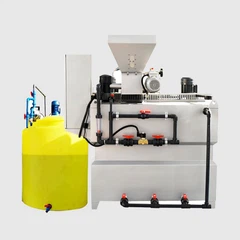
2.8 Pre-Processing
As with other submerged biofilm technologies, the feed water to MBBR requires proper pretreatment. In order to a good grate and sedimentation is necessary to avoid the long-term accumulation of nasty inert materials such as debris, plastics and sand in the MBBR. Since the MBBR is partially filled with carriers, these inert materials are difficult to remove once they enter the MBBR. When primary treatment is available, MBBR manufacturers generally recommend that the grate gap be no larger than 6 mm, and if no primary treatment is available, a fine grate of 3 mm or less must be installed. In addition, if the MBBR is added to the existing process, there is no need to add more grilles if the existing treatment level is already high.
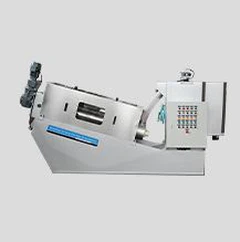
2.9 Solid-Liquid Separation Of MBBR
Compared to the activated sludge process, the moving bed process is very flexible from the point of view of subsequent solid-liquid separation large. The biological treatment effect of the moving bed process is independent of the solid-liquid separation step, so its solid-liquid separation units can be varied. In addition, the solids concentration of the MBBR effluent is at least one order of magnitude lower than that of the activated sludge process. Therefore, a variety of solid-liquid separation technologies have been successfully applied to MBBR, which can be combined with simple and efficient solid-liquid separation technologies such as air flotation or high-density sedimentation tanks where land is at a premium. In retrofitting existing wastewater treatment plants, the existing settling tanks may be used for solids separation in MBBR.
2.10 Considerations When Designing MBBR
The following is very important for the design of MBBR.
2.10.1 MBBR Traveling Flow Rate (Horizontal Flow Rate)
The peak flow rate (flow divided by reactor cross-sectional area) at peak flow through the MBBR must be considered in the design with a small flow rate (e.g. 20m/h), the carriers can be evenly distributed in the reactor. Too high travel flow rate (e.g. >35m/h), the carriers will accumulate at the interceptor grid and generate large head losses. Sometimes the hydraulic conditions at the peak flow rate will determine the geometry and number of series of MBBR. Consulting with the manufacturer and determining the appropriate travel flow rate is important for MBBR design. The aspect ratio of the reactor is also a factor. In general, a small aspect ratio (e.g., 1:1 or less) helps to reduce carrier drift toward the interceptor grid at peak flow rates and allows for a more uniform distribution of carriers within the reactor.
2.10.2 MBBR Tank Foam Problems
Foam problems are not common in MBBR, but are prone to occur during poor start-up or operation. Due to two partition wall in the middle of the continuous pool is higher than the water surface, so the foam will be limited to the MBBR. If foam must be controlled, the use of antifoam agents is recommended. The use of defoamers will cover the carrier and impede the diffusion of the substrate to the biofilm, which may affect the performance of the MBBR. Silicide defoamers should not be used as they are not compatible with plastic carriers.
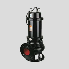
2.10.3 Carrier Bed Clearance And Temporary Storage
For well designed and built moving bed reactors, although failures are rare, it is prudent to out the problem of how to move the carrier out of the reactor and store it when the reactor is shut down due to maintenance, etc. should still be considered. All liquids in the reactor, including the carriers, can be drained by a 10cm concave wheel vortex pump. If the designed filling ratio is suitable, the carrier in one reactor can be temporarily moved to another reactor. However, the disadvantage of this method is that it is difficult to restore both reactors to their original filling ratios when moving the carriers back. Once the carriers are pumped back into the reactor, the only reasonable way to accurately measure the carrier fill ratio is to empty the reactor and measure the carrier height in both reactors. Ideally, there would be another pool or other unused unit that could be used as a temporary storage container for the carriers, so that the original reactor fill carrier ratio could be easily ensured.